


Views: 0 Author: Site Editor Publish Time: 2026-07-29 Origin: Site


Adding wind turbines, solar panels, and batteries does not guarantee stable power. Poor sizing or weak controls can still cause outages.
A reliable wind–solar–storage microgrid must balance changing generation, changing loads, and battery limits every second. Its components must also cooperate during faults and grid loss.
This guide explains how to define requirements, select an architecture, size Energy Storage, design controls, and verify safe operation.
Start by describing what “stable” means for your site. A factory may protect process equipment from short interruptions. A clinic may need several hours of critical-load backup. A remote community may require continuous islanded operation throughout difficult weather.
Set measurable targets before choosing equipment:
Define allowable outage time and annual service availability. Record the longest planned islanding period. Identify any loads unable to tolerate transfer delays.
Set acceptable voltage and frequency limits. Include motor starts, inverter ramps, and the largest expected load step.
Choose the main business goal. It may be resilience, renewable self-consumption, peak shaving, fuel savings, or several combined benefits.
Create three load groups: critical, flexible, and shedable. Critical loads receive first priority during limited generation. Flexible loads can shift into sunny or windy hours. Shedable loads disconnect before the battery reaches its protected reserve.
Do not size from monthly bills alone. Gather at least one year of interval data, preferably in 15-minute steps. Faster records help reveal motor starts, charging peaks, and brief disturbances. Add future loads, seasonal production changes, and planned electrification.
Use measured wind data at the proposed hub height. Nearby airport averages may misrepresent turbulence or obstacles. Solar estimates should include tilt, shading, temperature, soiling, and expected degradation.
Then align both resources against the same time-based load profile. Wind often adds value after sunset or during cloudy periods. However, complementarity must appear in local data, not marketing assumptions.
Component compatibility matters across the complete power path. Confirm voltage ranges, inverter behavior, controller protocols, and protection interfaces before procurement. Even proven devices can perform poorly when their operating assumptions conflict.
The finished baseline should contain load priorities, renewable profiles, outage targets, tariffs, environmental limits, and expansion plans. These inputs become the design contract for later simulations.
A stable architecture connects generation, conversion, storage, distribution, protection, and control. Each interface needs defined voltage, power, communication, and fault behavior. A missing interface specification can defeat otherwise reliable equipment.
Layer | Main Components | Stability Role |
Generation | Wind turbine, solar PV | Supplies complementary renewable power |
Energy Storage | Battery racks, BMS | Buffers ramps and reserves outage energy |
Conversion | Rectifier, DC/DC stage, PCS, hybrid inverter | Controls power flow and electrical output |
Distribution | Busbars, switchgear, breakers, transformers | Routes power and isolates faults |
Intelligence | EMS, microgrid controller, meters, weather data | Forecasts, dispatches, and coordinates assets |
An AC-coupled design connects separate wind, solar, and battery inverters to a common AC bus. It is flexible and suits retrofits. Extra conversions may reduce efficiency during renewable charging.
A DC-coupled design combines sources on a DC bus before one main inverter. It may reduce conversion stages and renewable clipping losses. Protection and vendor integration can become more specialized.
A hybrid layout mixes both approaches. Choose it when legacy AC assets must coexist alongside new DC generation or storage. Compare efficiency across actual energy paths, not one headline rating.
The Energy Storage - Innovative Solutions for Sustainability - GWZK includes batteries, hybrid systems, and inverter options. These categories may support different architectures. Final voltage windows, communication protocols, and protection settings still need verification.
Grid-following inverters need an existing voltage and frequency reference. They cannot always sustain an island alone. At least one source must form the grid during isolated operation.
A grid-forming battery inverter commonly establishes voltage and frequency. Other inverters then follow its reference. Define reserve power for step loads, reactive demand, and motor starting.
Also specify the point of common coupling. It needs an intertie breaker, synchronization controls, metering, and anti-islanding protection. The controller must recognize grid loss, open the intertie, stabilize the island, and reconnect safely afterward.
Annual energy balance can hide the hardest operating hour. Model solar output, wind output, and load on one timeline. Include forecast errors, equipment downtime, temperature losses, and seasonal resource gaps.
Run at least three cases: normal operation, low-renewable conditions, and a utility outage. Add a future-growth case when new machinery or electric vehicles are planned. A robust design meets critical loads without relying on perfect weather.
Battery power, measured in kW, determines how quickly storage can respond. Battery energy, measured in kWh, determines how long it can sustain that response. Both values must meet the mission.
Sizing Input | Design Question | Common Oversight |
Peak critical load | Can the PCS carry the island instantly? | Using average demand |
Largest load step | Can controls arrest frequency change? | Ignoring motor starts |
Required autonomy | How long must usable energy last? | Using nameplate kWh |
Renewable deficit | How much energy bridges poor weather? | Assuming daily sunshine |
SOC reserve | What capacity remains for outages? | Spending all capacity on savings |
Degradation margin | Will targets remain achievable later? | Designing only for year one |
Usable capacity must reflect state-of-charge limits, depth of discharge, temperature, aging, and round-trip efficiency. Include auxiliary consumption from HVAC, controls, fire systems, and transformers. These loads continue during islanding.
For a first estimate, multiply critical-load energy by required autonomy. Then adjust for conversion losses, permitted discharge, reserve margin, and battery aging. Simulation should replace this rough estimate before procurement.
More batteries do not always improve project value. Additional wind capacity may cover winter or nighttime deficits. Additional solar may charge storage more cheaply during predictable daytime windows.
Use sensitivity analysis across several wind, solar, and battery combinations. The Microgrid Design Toolkit – Energy compares site-specific cost, performance, and reliability. Similar modeling tools can test tradeoffs before capital is committed.
Check inverter clipping, battery C-rate, cycle count, curtailed renewable energy, unmet load, and generator runtime. The preferred design should remain stable after one major component becomes unavailable.
The energy management system handles slow decisions across minutes or hours. It forecasts load and renewable generation, schedules charging, manages tariffs, and protects an outage reserve. The microgrid controller manages faster coordination and operating transitions.
A practical dispatch order may follow these rules:
1. Serve current loads from available wind and solar power.
2. Charge Energy Storage using safe power and SOC limits.
3. Export or curtail surplus power after storage priorities are met.
4. Discharge during deficits, expensive periods, or grid disturbances.
5. Shed lower-priority loads before the protected SOC floor is breached.
Fixed rules provide a dependable fallback. Forecast-based optimization can improve savings and renewable use. Never let economic dispatch consume the capacity reserved for resilience.
Power balance affects frequency immediately during islanded operation. Reactive power and network conditions affect voltage. Grid-forming controls must respond before supervisory software completes a new schedule.
Use droop control or another validated sharing method across parallel sources. Define active and reactive power limits for each inverter. Check harmonics, unbalance, fault ride-through, and low-inertia behavior.
The DOE microgrid building-block guidance connects conversion, control, protection, islanding, communications, and storage. Treat those functions as one coordinated design.
Document sequences for grid loss, planned islanding, black start, resynchronization, and communication failure. Each sequence needs clear timing, permissives, and fallback states.
During black start, the grid-forming source energizes the bus first. Loads and renewable inverters return in controlled blocks. This prevents transformer inrush or motor starts from collapsing voltage.
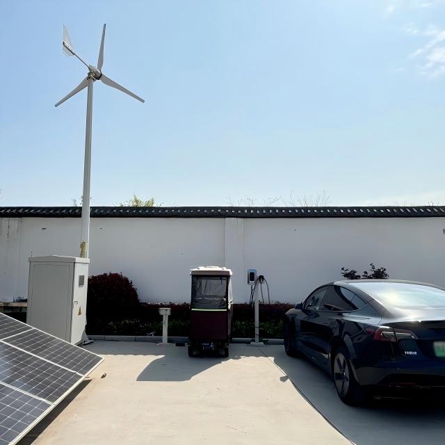
GWZK’s 1kW All-in-One Wind-Solar Storage Charging System integrates wind, PV, LFP storage, BMS, control, and inverter functions. It illustrates the coordination principle for small loads. Larger systems require project-specific control studies and redundant communications.
Inverter-based resources often provide lower fault current than the utility grid. Traditional overcurrent settings may therefore miss islanded faults. Protection must adapt to both grid-connected and islanded conditions.
Complete short-circuit, protection-coordination, grounding, arc-flash, harmonic, and transient studies. Verify transformer energization, motor starts, renewable ramps, and abrupt load changes. Review utility interconnection rules and local fire requirements before final equipment selection.
Separate critical-load panels from noncritical feeders. This makes selective load shedding faster and more predictable. Hardwired protection should remain effective if the EMS or communications network fails.
Factory acceptance tests verify equipment and communication logic. Site acceptance tests verify the installed system. Commissioning must recreate difficult events, not only normal power flow.
Test these conditions under controlled procedures:
Loss of the utility grid at several load levels.
Sudden loss of solar, wind, battery, or a major feeder.
Largest expected load step and motor start.
Low SOC, sensor failure, and communication loss.
Black start, staged load pickup, synchronization, and reconnection.
Emergency shutdown, alarms, fire-system interfaces, and manual control.
Record frequency nadir, voltage recovery, transfer time, SOC response, and load-shedding order. Correct unstable behavior before commercial operation.
Monitor renewable yield, curtailed energy, battery temperature, cell imbalance, inverter alarms, round-trip efficiency, and unmet-load events. Compare actual results against the design model each month.
Update EMS forecasts after seasonal changes or major load additions. Recheck the protected SOC reserve before severe weather. Inspect switchgear, cooling, turbine hardware, PV connections, and battery safety systems under planned schedules.
Cybersecurity belongs in routine operation. Segment control networks, limit remote access, manage credentials, and test backups. Maintain a manual operating procedure for lost communications.
A stable microgrid improves through measured operation. Trend data can reveal dirty panels, turbine underperformance, battery aging, or poor dispatch before reliability suffers.
A stable wind–solar–storage microgrid begins with measured loads and local resource data. Coordinated sizing, grid-forming controls, protection, and realistic testing keep it dependable.
Energy Storage should serve both fast stability and long-duration resilience. For a site-specific configuration, contact GWZK and compare the proposed design against your operating targets, local codes, and lifecycle budget.
A: Balanced capacity, grid-forming control, protected battery reserves, coordinated protection, and tested operating transitions create stable performance.
A: Size battery kW for peak response and kWh for required autonomy, losses, reserve, aging, and usable discharge.
A: Yes, if it has grid-forming capability, sufficient generation, storage, protection, black-start logic, and prioritized loads.
A: LFP batteries offer strong thermal stability, long cycle life, and practical performance for stationary daily cycling.
A: Test grid loss, source trips, load steps, low SOC, communication failure, black start, protection, and reconnection.


